LDR — opcode $F0
LDR Rn,addr — R2 ← addr; Rn.hi ← [R2]; Rn.lo ← [R2+1]; R2 ← addr+1
| Operands | Bytes | Microcode steps |
|---|---|---|
| Rn,addr | 3 | 19 |
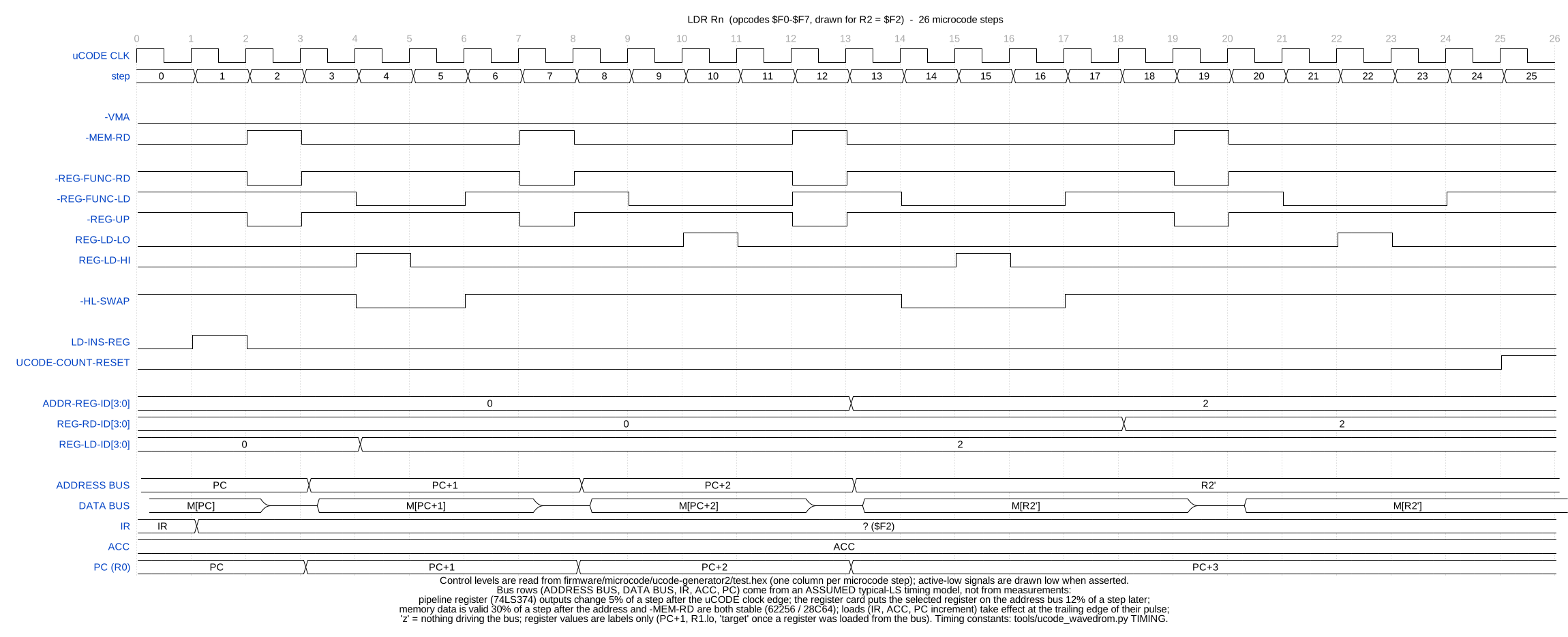
One column per microcode step. The control lines are read from the microcode image; the address bus, data bus and registers at the bottom are a model. How to read the diagrams · the instruction set
← STR ($E8) · All opcodes · INTE ($FB) →
Last updated 6 November 2026